
×

Top 10 Analog Splitter 4 20mA Types for Global Buyers?

Global buyers need more than a polished product list when selecting an Analog Splitter 4 20ma for process control systems. A splitter may separate one transmitter signal into two outputs, but small specification gaps can create expensive field problems. Input burden, loop power, isolation voltage, accuracy, response time, and temperature range all deserve close attention. A unit that performs well in a clean laboratory may behave differently beside a variable-frequency drive or long shielded cable.

Instrumentation specialist Jonas Berge has emphasized a practical principle: “Reliable measurements begin with understanding the complete signal path, not just the transmitter.” That viewpoint guides this review. The following Top 10 Analog Splitter 4 20mA types are compared through real purchasing concerns, including two-wire compatibility, active or passive outputs, galvanic isolation, DIN-rail mounting, surge protection, and international documentation. Some models suit compact control cabinets. Others are better for harsh outdoor panels, redundant PLC inputs, or multi-vendor installations.

A neat ranking can mislead.

There is no universal winner. A low-cost splitter may offer excellent accuracy but lack certified isolation. Another model may support broad power ranges yet require careful grounding. Buyers should check terminal labeling, loop resistance, calibration data, and replacement availability before approving a purchase. Regional voltage standards and local installation practices also matter. This guide aims to make the shortlist clearer, while admitting one limitation: datasheets cannot replace a measured loop test under actual operating conditions.
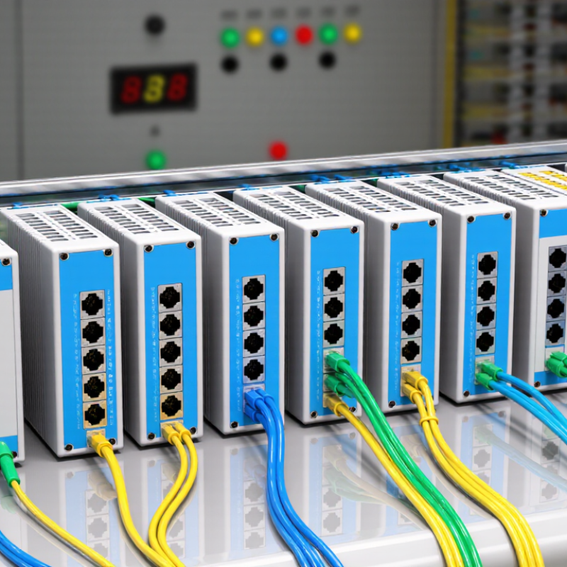
Top 10 Analog Splitter 4 20mA Types for Global Buyers?

What Is a 4–20 mA Analog Splitter and How Does It Work?

A 4–20 mA analog splitter receives one industrial current signal and creates two or more usable output signals. It commonly serves controllers, displays, recorders, or alarm systems at the same time. The 4 mA level usually represents zero measurement, while 20 mA represents the calibrated maximum. Ten common splitter types include active, passive, loop-powered, isolated, non-isolated, single-input, dual-output, DIN-rail, compact, and high-accuracy models. The right type depends on wiring distance, output load, power availability, and signal isolation needs.

Inside the device, the splitter senses the input current and reproduces proportional output currents. An isolated design separates circuits electrically, reducing ground-loop problems and protecting connected instruments. During practical commissioning, technicians should verify input range, output range, terminal polarity, supply voltage, and maximum loop resistance. Small errors often appear when several receivers share one signal. A splitter is not automatically accurate. Calibration quality, temperature drift, and installation habits matter too. This is where product datasheets deserve careful reading, not quick assumptions.

Tips: Choose isolation for separate control cabinets or long cable runs. Confirm each output’s load capacity before installation. Test 4 mA, 12 mA, and 20 mA with a calibrated source. Record the results. If a signal behaves strangely, check grounding before replacing the splitter. Sometimes the wiring is the real problem.

Key Types of 4–20 mA Analog Splitters for Industrial Applications

Top 10 Analog Splitter 4–20mA Types for Global Buyers

Industrial plants increasingly depend on stable 4–20 mA signal distribution. Grand View Research estimates the industrial automation market could grow at a 10.5% CAGR through 2030. Fortune Business Insights also forecasts strong expansion in industrial automation. These figures support continued demand for dependable analog splitters.

The main types include passive splitters, active splitters, loop-powered units, isolated splitters, non-isolated splitters, DIN-rail models, compact panel units, programmable splitters, HART-transparent splitters, and high-density multi-channel versions. Active models suit long cable runs and multiple receivers. Isolated types help reduce ground loops between controllers, transmitters, and displays. HART transparency matters when technicians need digital diagnostics over the analog loop. Some classifications overlap. That is a practical weakness in many product comparisons.

Tips: Confirm input impedance, output load, accuracy, isolation voltage, and power requirements. A two-output splitter may not drive two distant devices reliably without external power. Check whether the 4 mA live-zero signal remains stable during faults. In field testing, wiring errors are often more common than module failure. Select a temperature range for the cabinet, not the office. IEC 61326-1 compliance supports electromagnetic compatibility, but installation quality still matters. Do not assume every programmable model supports HART pass-through. Verify it.

Top 10 Analog Splitter Types for Global Buyers

Analog splitter types help global buyers distribute one 4–20 mA signal to several control devices. Common options include passive splitters, active splitters, isolated splitters, and loop-powered models. Each type suits a different panel design, wiring distance, and power arrangement.

Passive units are simple and economical, but they depend heavily on loop resistance. Active splitters use external power and usually provide stronger signal stability. Isolated splitters add electrical separation between input and outputs, which helps reduce ground-loop problems in noisy plants. DIN-rail versions save cabinet space, while compact field-mounted types suit remote junction boxes. During panel testing, technicians should check zero, span, output load, and terminal polarity. Small wiring errors can create large control deviations.

Tips: Confirm whether the input is active or passive before ordering. Check each output’s current capacity and isolation rating. For international projects, review terminal spacing, enclosure conditions, temperature range, and required conformity documents. A wide supply range can simplify regional installation. Still, it may not solve poor grounding. Do not select by channel count alone; a four-output device may perform worse than a two-output model under heavy loads. Specifications can look clear, yet installation conditions often expose missing details. Ask for test data, wiring diagrams, and calibration procedures before approval.

Top 10 Analog Splitter 4–20 mA Types for Global Buyers

No. Splitter Type Typical Signal Path Isolation Power Requirement Typical Accuracy Typical Response Time Common Applications Key Buying Consideration
1 Active 1-to-2 Analog Splitter One 4–20 mA input to two independent 4–20 mA outputs Usually input-to-output and output-to-output isolation External DC supply, commonly 18–32 VDC Approximately ±0.1% of span Typically 10–30 ms Sending one transmitter signal to a PLC and a control system Verify output load capacity and the number of isolated channels
2 Active 1-to-3 Analog Splitter One 4–20 mA input to three separately powered outputs Normally galvanically isolated on each output External DC supply, commonly 18–32 VDC Approximately ±0.1% to ±0.2% of span Typically 10–40 ms Process control, alarm monitoring, recording, and indication Check total power consumption, terminal layout, and enclosure width
3 Passive Loop-Powered Splitter One 4–20 mA loop distributed to two passive outputs Often non-isolated; isolated versions require careful loop-power design Powered by the current loop; no separate supply in basic designs Approximately ±0.2% to ±0.5% of span Typically 20–100 ms Low-power field instruments and retrofit installations Calculate loop voltage drop and confirm the available compliance voltage
4 Galvanically Isolated Splitter One input with electrically separated output circuits Input, output 1, and output 2 are electrically isolated External DC supply, commonly 18–32 VDC Approximately ±0.1% to ±0.2% of span Typically 10–30 ms Breaking ground loops and protecting control equipment Review isolation voltage, common-mode limits, and EMC specifications
5 Non-Isolated Signal Splitter One 4–20 mA input buffered into two outputs sharing a common reference No galvanic isolation between circuits External DC supply, commonly 12–32 VDC Approximately ±0.1% to ±0.3% of span Typically below 20 ms Cabinet systems with a common grounding and power arrangement Use only where ground-potential differences are not a concern
6 HART-Transparent Splitter 4–20 mA signal duplication while allowing HART communication to pass Usually isolated; design-dependent External DC supply is typical Approximately ±0.1% to ±0.2% of span Typically 10–50 ms for the analog signal Smart transmitters requiring simultaneous control and configuration access Confirm HART pass-through, input impedance, and communication wiring method
7 DIN-Rail Analog Splitter Compact 4–20 mA distribution module for control cabinets Isolated or non-isolated, depending on the circuit design Commonly 18–32 VDC Approximately ±0.1% to ±0.3% of span Typically 10–40 ms PLC, DCS, SCADA, and panel-mounted instrumentation Check DIN-rail dimensions, terminal spacing, heat dissipation, and wiring access
8 Explosion-Protected Splitter 4–20 mA signal duplication for hazardous-area instrumentation Typically galvanically isolated External DC supply; intrinsically safe systems have energy limitations Approximately ±0.1% to ±0.3% of span Typically 10–50 ms Oil and gas, chemical processing, and dust or gas hazardous areas Verify the exact hazardous-area certification, zone classification, and wiring rules
9 High-Density Multi-Channel Splitter Multiple independent 1-to-2 or 1-to-3 channels in one enclosure Channel isolation varies; individual channel isolation is preferable Shared external DC supply is common Approximately ±0.1% to ±0.2% of span Typically 10–40 ms Large control panels and systems with limited cabinet space Compare channel density, per-channel diagnostics, thermal load, and spare capacity
10 Universal Input Signal Splitter Configurable input for 4–20 mA, voltage, RTD, or thermocouple signals with 4–20 mA outputs Often isolated, subject to the selected input and output configuration External DC supply, commonly 18–32 VDC Approximately ±0.1% to ±0.3% of span Typically 20–100 ms Mixed-signal projects, replacement stock, and changing process instrumentation Check configuration software, sensor compatibility, cold-junction compensation, and calibration method

Note: Electrical performance varies by circuit design, ambient temperature, load resistance, power supply, calibration, and applicable regional certification requirements. Verify the manufacturer’s technical datasheet before purchase or installation.

How to Compare Accuracy, Isolation, Wiring, and Power Requirements

Selecting among the top 10 analog 4–20 mA splitter types requires more than checking catalog accuracy. IEC 60381-1 defines the current signal range, while NAMUR NE 43 identifies 3.6 mA and 21.0 mA as useful fault limits. A practical splitter should preserve these diagnostic levels without clipping. Compare stated accuracy, linearity, temperature drift, and response time. A 0.1% error can equal 0.016 mA across a 16 mA span. That may matter when a transmitter controls a narrow process window.

Isolation deserves equal attention. Three-way isolation separates input, output, and power circuits, reducing ground-loop risk in long cable runs. Check the isolation test voltage, working voltage, and common-mode limits. These values are not interchangeable. For wiring, verify loop-powered or externally powered operation. A two-wire loop may simplify field installation, but it has a tighter voltage budget. Calculate supply voltage, transmitter drop, splitter burden, and cable resistance before approval. A 24 VDC supply often appears generous. It may not be.

Tips: Map each channel before purchasing. Record input type, output count, terminal polarity, cable length, and required load resistance. Check whether the splitter supports sinking or sourcing outputs. Review performance at low temperatures, not only at 23°C. Also, question impressive accuracy claims. Some figures exclude wiring resistance, warm-up time, or calibration uncertainty. That omission can weaken an otherwise careful comparison. Test one unit with a calibrated current source and a precision meter before deploying ten.

Top 10 Analog 4–20 mA Splitter Types for Global Buyers

Representative comparison of common industrial architectures. Accuracy is shown as ±% of span, isolation as kVrms, supply as VDC, and wiring as the number of input channels. Lower accuracy values indicate better precision. Loop-powered units use the signal loop instead of a separate power supply.

Buyers should verify the final datasheet for temperature drift, load capacity, hazardous-area certification, terminal arrangement, and whether isolation is provided between input, output, and power circuits.

Selection Standards, Installation Factors, and International Compliance

Top 10 Analog Splitter 4–20mA Types for Global Buyers

Selection Standards, Installation Factors, and International Compliance

The ten common types include passive, active, powered, isolated, non-isolated, one-in/two-out, and one-in/four-out splitters. DIN-rail, field-mount, and configurable models complete the practical selection range. Choose according to signal source, output count, and available loop power. A passive splitter may suit simple panels, while an active unit handles heavier output loads. Galvanic isolation is valuable when ground differences or electrical noise threaten measurement stability. Check input impedance, output drive capacity, accuracy, temperature drift, and response time before ordering. A low-cost unit can become expensive after rewiring.

Installation details often decide whether a splitter performs well. Keep signal cables away from motor wiring and switching conductors. Use shielded twisted pairs where noise is likely. Ground the shield at one controlled point, not randomly at both ends. Confirm polarity, terminal markings, fuse protection, and enclosure spacing. Measure the loop current before connecting instruments. A 24 VDC supply may not provide enough voltage after cable and load losses. Leave ventilation space around heat-producing modules. Small errors matter.

International buyers should request electrical ratings, test reports, wiring diagrams, and traceable calibration information. Verify applicable requirements for EMC, electrical safety, environmental conditions, and hazardous-area use. Common references may include IEC 61326 and IEC 61010, but market acceptance differs by destination. Do not assume a conformity mark proves suitability for every installation. Documentation should match the exact model and revision. One practical weakness remains: catalog accuracy may not reflect field conditions. Review actual cable length, ambient temperature, and maintenance skills before final approval.

Article Source: