
×

How to Choose a Pneumatic Conveyor for Your Business?

A Pneumatic Conveyor can move powders, granules, and other bulk materials through enclosed pipelines, helping keep floors clearer and reduce manual handling. But choosing a system is not simply a matter of selecting a blower and pipe diameter. Material properties shape the design. Fine flour behaves differently from plastic pellets, while damp or fragile products may need special care. The distance, elevation changes, bends, and required throughput also affect performance. Small details count.

Start by defining what the system must carry and how often. Record the material’s bulk density, particle size, moisture, temperature, and tendency to abrade or break. Then map the route and estimate the required capacity, including peak demand rather than only average production. Conveying mode matters, too: dilute-phase systems move material at higher air velocities, while dense-phase options may suit some heavier or more fragile materials. Neither is automatically the better choice. Ask suppliers to explain assumptions, expected energy use, filtration needs, and maintenance access. Request testing when material behavior is uncertain; a sample run can reveal issues that a brochure cannot. That assumption can be wrong.

A sound selection balances product quality, operating costs, reliability, and future changes in production. Compare the complete installation, not just the purchase price. Check how operators will inspect filters, clear blockages, and monitor pressure. Leave room for real-world variation, because feed rates and material conditions rarely stay perfect. With clear requirements and a qualified engineering review, businesses can narrow their options and choose a Pneumatic Conveyor that fits the process rather than forcing the process to fit the equipment.
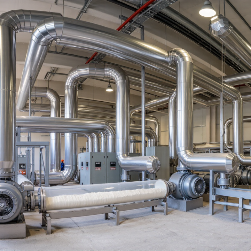
How to Choose a Pneumatic Conveyor for Your Business?

Define Required Capacity (t/h), Conveying Distance, and Vertical Lift

A pneumatic conveyor should be sized around the material and the real production target, not just a machine’s nameplate rate. Define required capacity in tonnes per hour, including short periods when upstream equipment runs faster. If a line must move 12 t/h continuously but receives surges of 15 t/h, designing only for the average can create backups. Check bulk density, particle size, moisture, and how easily the product breaks. A fine powder behaves differently from coarse pellets. Small details matter.

Measure the conveying distance along the actual pipe route, including bends and horizontal sections. A 40-metre path with several elbows can demand more airflow than a simple straight run of the same length. Record where the material enters and where it must discharge. Then measure vertical lift from the pickup point to the receiving vessel; do not estimate it from a floor plan. Measure the route.

Capacity, distance, and lift interact, so changing one can affect the others. Ask a supplier or process engineer to review the material data and layout before choosing a system. Share peak and normal throughput, pipe length, bend count, and lift height. Be precise, but leave room for uncertainty: actual material behavior may differ from a sample test. That part is easy to underestimate. A site trial or documented test basis can help confirm the design before installation.

How to Choose a Pneumatic Conveyor for Your Business? — Define Required Capacity (t/h), Conveying Distance, and Vertical Lift

Material / Application Indicative Capacity (t/h) Conveying Distance (m) Vertical Lift (m) Common Conveying Approach Key Selection Consideration
Flour and other fine food powders 2–8 20–60 5–15 Dilute-phase, typically with filtration at the receiving point Control dust and product degradation; confirm food-contact and cleaning requirements.
Plastic pellets 3–15 30–100 5–25 Dilute-phase or low-velocity conveying Low conveying velocity can help limit pellet breakage and fines; consider pickup and receiver layout.
Grain and granular agricultural products 5–25 20–80 5–20 Dilute-phase conveying Check particle size, moisture, dust characteristics, and the allowable amount of product damage.
Cement and similar fine powders 10–40 50–150 10–30 Dense-phase or dilute-phase, depending on route and equipment Account for abrasive wear, air demand, pressure loss, and dust collection at the destination.
Fly ash and other dry, fine mineral powders 10–50 50–200 10–40 Often dense-phase for longer routes or when low conveying velocity is preferred Confirm powder flowability, temperature, bulk density, and the pressure required for the full route.
Fine mineral products and powdered additives 5–20 30–120 5–25 Dilute-phase or dense-phase, selected for material and route Evaluate abrasiveness, particle-size distribution, and whether the material is cohesive or prone to settling.

Planning note: These figures are indicative preliminary ranges, not guaranteed equipment ratings. Actual capacity and pressure requirements depend on material properties, pipeline diameter and layout, bends, feed conditions, air supply, and operating method. Confirm the design with material-specific testing and a detailed system calculation.

Characterize Particle Size, Bulk Density (kg/m³), Moisture, and Abrasiveness

Particle size is a practical starting point when choosing a pneumatic conveyor. Fine powder can become airborne easily, while coarse granules may need more conveying air to stay in motion. Record the full size range, not just the average. A few oversized particles can change flow behavior. Test a representative sample if the material varies between batches.

Bulk density, measured in kg/m³, helps estimate how much material a line must carry. But density alone does not tell the whole story. Check moisture content, since damp powder may cling to pipe walls or form lumps. Note whether the material absorbs moisture during storage. Abrasiveness matters too: sharp, hard particles can wear bends and elbows faster than straight pipe. Ask operators to inspect likely wear points during trials. Small details count. A spreadsheet may make the selection look certain, yet actual flow can differ from a laboratory sample. Conveying distance, bends, and feed consistency also affect performance. Use measured material properties to guide the design, then confirm it with a controlled test before committing to a full installation.

How to Choose a Pneumatic Conveyor for Your Business?

Characterize particle size, bulk density (kg/m³), moisture, and abrasiveness before selecting a conveying system.

Bulk density affects the mass a conveying line must move, while particle size, moisture, and abrasiveness influence airflow needs, plugging risk, and equipment wear. Values shown are representative approximations; actual properties vary with grade, handling, and measurement method. Test your material and confirm design conditions with a conveying specialist.

Compare Dilute-Phase (15–35 m/s) and Dense-Phase (3–10 m/s) Conveying

How to Choose a Pneumatic Conveyor for Your Business?
Compare Dilute-Phase (15–35 m/s) and Dense-Phase (3–10 m/s) Conveying

Choosing between dilute-phase and dense-phase conveying starts with the material, not just the speed. Dilute-phase systems move particles in a fast air stream, typically at 15–35 m/s. They can suit powders or granules that tolerate more movement. But higher velocity may increase particle breakage, pipe wear, and dust concerns. Picture a fragile pellet passing through several bends: the route can matter as much as the speed. Check particle size, bulk density, moisture, and required throughput before comparing equipment.

Dense-phase systems convey material more slowly, generally at 3–10 m/s, often in concentrated slugs or plugs. Lower speed can reduce degradation and abrasion for suitable materials, though it does not guarantee gentle handling. Some products may bridge or move inconsistently, so trials and careful system design matter. Dense-phase equipment may also need higher pressure and specialized feeding. Not a simple swap. Map the pipeline length, bends, elevation changes, and batch pattern, then ask suppliers for operating data using material like yours. A clean spreadsheet can still hide one awkward elbow or a damp feed point.

Choose Pressure or Vacuum Conveying for the Feed and Discharge Layout

A pneumatic conveyor should follow the feed and discharge layout, not just the shortest pipe route. Pressure conveying pushes material from a central feed point toward one or more destinations. It can suit a plant with a fixed hopper and distant silos. Branch lines and diverter valves add flexibility, but uneven flow can complicate control. Measure the route.

Vacuum conveying pulls material from several pickup points to a central receiver. This arrangement can help when bags, bins, or process machines feed one collection area. The receiver needs space for a filter, solids discharge, and maintenance access. Small details matter. A poorly placed receiver can make cleaning and bin changes awkward.

Energy deserves attention, too. The U.S. Department of Energy’s Improving Compressed Air System Performance: A Sourcebook for Industry reports that compressed-air systems use about 10% of electricity in U.S. manufacturing, though plant conditions vary. That figure is not a direct comparison of pressure and vacuum systems. It is a reminder to check air demand, operating hours, material bulk density, and conveying distance before choosing. Treat layout rules as a starting point; actual material tests may reveal surprises.

Check Airflow, Filter Rating, Energy Use, and Wear Against Supplier Test Data

How to Choose a Pneumatic Conveyor for Your Business?

Choose by measured performance, not brochure capacity. Ask suppliers to test your material at the planned line length, lift, bends, and feed rate. Record airflow and conveying pressure at steady operation, then compare them with your actual duty point.

A high filter rating alone is not enough. Request the filter efficiency class, pressure drop when clean and loaded, and downstream dust levels. ISO 8573-1 classifies compressed-air purity, but it does not prove a filter suits your material or process.

Energy can change the payback. The U.S. Department of Energy’s Improving Compressed Air System Performance guide reports that compressed air may account for up to 10% of industrial electricity use. Ask for measured power at your operating point, not motor nameplate power. Include leaks, filter loading, and idle periods in the estimate.

For wear, request test records showing particle size, bulk density, moisture, throughput, and run time. Inspect elbows and bends after testing; a good efficiency figure may hide rapid erosion in one tight turn.

Tips: Send suppliers a representative sample, including fines and damp material. Ask for filter pressure readings before and after the test, plus a wear inspection after a defined run. Keep the test setup close to your plant layout. If it is not, treat the result as a clue, not a guarantee. Test it onsite.